Behavioural State Machines
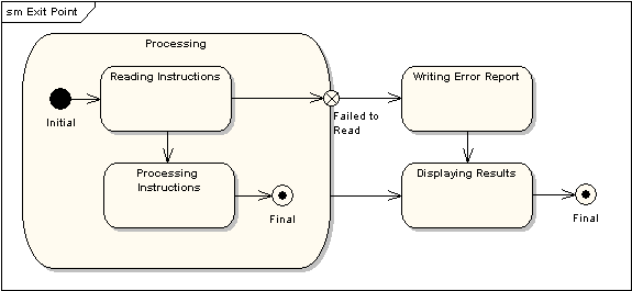
Example State Machine Diagram
A state machine represents the internal states of a single object and how it transitions between those states in response to events.
- States: Different conditions or modes an object can be in (e.g., “new patient,” “current patient”).
- Transitions: The movement from one state to another, often triggered by an event.
- Events: Triggers for state transitions (e.g., “patient check-in”).
Usage
- Typically used for complex objects that go through multiple states.
- Focuses on how an object’s internal attributes change over time, such as a patient’s status moving from new to treated.
Components
- States
- Initial State: Represented by a filled black circle, it indicates where the state machine begins.
- Final State: Depicted as a filled black circle inside a larger circle, it signifies the completion of the state machine’s operation.
- Stable States: Intermediate states that an object can occupy throughout its lifecycle.
- Transitions
- Arrows connecting states, indicating the movement from one state to another.
- May include guard conditions that determine whether the transition can occur based on specific criteria.
- Events
- Triggers that cause a transition to occur, often labeled on the transition arrow.
- Examples include user actions, system events, or time-based triggers.
- Actions
- Behaviors that occur as a result of a transition.
- Actions can be associated with transitions or can happen on entering or exiting a state.
Guidelines for Creating State Machines:
- Ensure all states are reachable.
- Avoid “black holes” (states from which objects can’t exit) and “miracles” (unexplained transitions).
- Transitions should be clearly tied to specific messages or operations.